
Splicing: what it saves, what it costs, and where it may not fall
Contents — 6 sections
Splicing is the one cutting parameter that is not really about cutting. Allow a part to be carried across more than one stock bar and the optimiser gains a great deal of freedom, because it no longer has to find a bar with room for the whole thing. Waste falls, sometimes sharply.
It also means somebody welds two pieces of structural steel together and the result carries load. That belongs to your welding practice and your structural requirements, which is why the setting stays off until you turn it on.
Splicing and its restrictions are not on every plan, and restrictions derived automatically from DSTV files additionally depend on the DSTV import. The comparison matrix is the authority on which tier carries which.
The four parameters
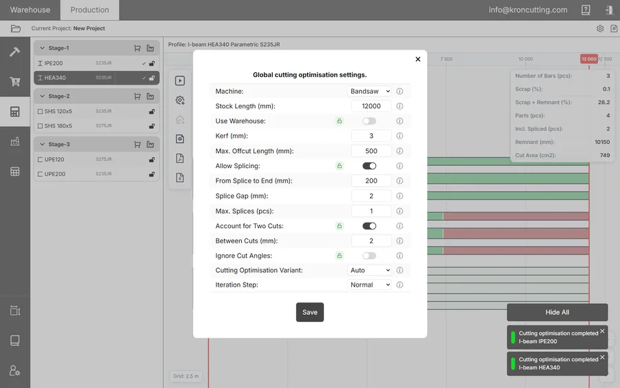
Allow Splicing is the switch. Turning it on brings three further parameters into play.
From Splice to End (mm) is the minimum distance from the part's edge within which no splice may fall. A weld at the very end of a member is usually awkward to make and structurally undesirable, and this value keeps the algorithm away from the edges.
Splice Gap (mm) is the technological allowance for the splice itself, the material the optimiser sets aside so the joint can be prepared and made. Take it from what your shop actually does rather than from a round number.
Max. Splices (pcs) limits how many times a single part may be divided: one allows the part to become two pieces, two allows three, and so on. The algorithm always aims for the fewest pieces it can manage, so raising the ceiling does not mean it will be used. It only permits the division when the material saving justifies one.
Where a splice may not fall is a separate question
Those four parameters are global. They describe how your shop splices in general and say nothing about this particular part having a hole 400 mm from one end.
That belongs to the part, and it is set when the part is added. KRON Cutting calls these splice restrictions and will refuse to place a splice inside a zone you have described. Three methods are available: a specific interval in millimetres, a percentage at the edges, or a percentage in the centre. Overlapping restrictions are merged automatically, so describing the same zone twice from two directions does no harm.
One practical warning: avoid changing a part's length after adding restrictions. KRON will warn you if the change affects an existing restriction, but a restriction expressed as an interval means something different on a part 400 mm longer, and the warning is easier to heed than to undo.
The restrictions you do not have to type
Where parts arrive by DSTV import, the restriction zones can be derived from the files instead of being entered by hand. The import dialog offers five, each with its own constraint length: forbid splicing in hole zones, in part connection zones and in part cut-out zones, plus no splice at the ends of the part or in its centre, both expressed as a percentage of length.
On a large drawing set this is much the fastest route to correctness, with one caveat worth establishing before you depend on it. The automatic part-connection restriction will not work unless the additional settings were configured during export from Tekla. The geometry arrives either way; the connection data does not. Switching the toggle on in KRON against an export written without those settings gives you a restriction that silently constrains nothing.
The optimiser that produces more waste on purpose
KRON offers three optimisation variants, and the second exists because of splicing:
- Opt. 1 reduces the amount of waste.
- Opt. 2 reduces the number of splices.
- Auto runs both and returns whichever consumed less material. It is slower, since it does the work twice.
Opt. 2 will hand you a plan that wastes more steel, which is its purpose. A splice costs welding time, consumables, an inspection in some shops and a structural justification in others. Somewhere there is a crossover point past which the extra waste is cheaper than the joint, and where that point sits depends on your welding cost and your requirements. KRON has no way of knowing either.
The practical approach is to run Auto once on a representative job and look at what the two variants produced. The results table gives the comparison directly: Incl. Spliced (pcs) counts the parts assembled from more than one piece, against Scrap (%) for what avoiding them cost in material. Price both in your own numbers once and you will know which variant to run for the rest of the year.
Reading a spliced plan
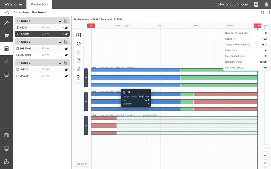
On the result, parts that have been split into pieces share a unique colour across all their pieces. Left-clicking a colour highlights every piece of that part and greys out the rest, which is the quickest way to see where a given member ended up; right-clicking the result field clears the selection. Hovering a piece shows its main information.
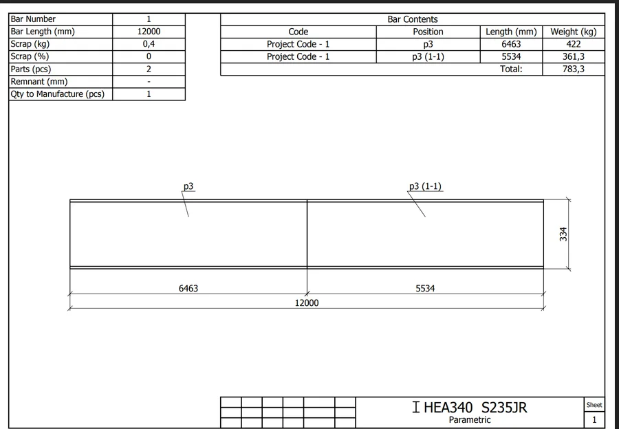
The drawings carry the splice through to the floor. Two drawing settings exist for it: Part Segment Prefix, applied to the name of a spliced part's piece, and Splice Variant Prefix, applied to the sequence number of a shop splice of identical parts on each piece. Set them to whatever your fabricators already read instead of teaching the floor a new convention.
When to leave it off
Splicing is not a free optimisation. Leave it off where the members are structurally critical and a joint would need justification you would rather not produce for every job, where welding capacity is the constraint instead of the steel budget, or where the parts are short enough that the extra freedom buys very little.
When it is on, treat the three sub-parameters as a description of your practice rather than a tuning knob. From Splice to End and Splice Gap encode what your shop can physically do, while Max. Splices is the only one of the three that is genuinely a policy choice.