
Production module
The Production module is where a job is planned: parts go in, a cutting plan comes out, and a production document carries it to the floor.
Projects
Entering the module offers you a new project or one you created earlier. Each project shows its name, creator and date, and can be deleted or locked against changes by other users.
After creation a project is editable by everyone. Clicking the open lock in the Shared column closes it — from then on only you can edit it, while others can view the project and save the result.
- The administrator manages the availability of all projects.
- An employee manages only the projects they created themselves.
The work tabs
The left-hand rail holds the tabs you move through in order:
- Adding Parts — the hammer icon
- Adding to Cutting — the basket with a down arrow
- Cutting — the calculator icon
- Production Documents — the factory icon
- Sheet cutting — under development
Adding parts
The tab is split into Drawing Sets, Profiles, and the working area.
Drawing sets
Click the plus next to Drawing Sets and give the set a name — normally the project code. Drawing sets exist so you can filter parts and so the plant can produce several orders at once.
To get the least waste, put as many parts of the same profile and material as possible into the optimiser together, even across different orders. More parts means more ways to combine them, which means a tighter nest. A drawing set that contains one order's worth of one profile has very little for the optimiser to work with.
Profiles and materials
You only need to enter materials and profiles by hand when you are adding parts by hand. Imports bring their own. Before entering profiles, prepare the set's materials with the Manage materials button on the Profiles panel — see Materials and aliases.
Adding parts by hand
Button: the cube with a right arrow, labelled kron, at the top of the screen.
Select a drawing set first, or the button stays inactive.
- Click the button to open the bulk-add Parts window.
- For each part enter position, quantity, length and profile. Cut angles become available once a profile is set. The right-hand column has copy and delete buttons for the row.
- Set the cut angles — see Cut angles.
- If needed, set splice restrictions at the bottom of the window. KRON will then refuse to place a splice in the zone you have described. Three methods are available: a specific interval, a percentage at the edges, or a percentage in the centre. Overlapping restrictions are merged automatically.
- Click Add parts to the set.
Try not to change a part's length after adding restrictions. If the change affects an existing restriction, KRON will warn you.
To inspect a part, click the eye icon at the top right — it opens a drawing built from the parameters, with 2D and 3D modes.
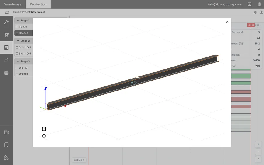
Adding parts from DSTV
Button: the file icon labelled dstv. Not available on all plans.
This transfers data from Tekla Structures — and any other program that writes the DSTV standard — into KRON, recognising all part characteristics automatically.
- Choose the File Encoding. There are hints next to the selector about which Tekla versions use which; UTF-8 covers Tekla 2016 and later, Advance Steel and most modern software.
- Set the splice constraints you want derived from the files. The options are: forbid splicing in hole zones, in part connection zones, and in part cut-out zones, each with a constraint length in millimetres; and no splice at the ends of the part or in its centre, each as a percentage of length.
- Select the NC files. Loading can take a while. KRON adds the profiles and materials it finds to the drawing set as it goes.
Things worth knowing:
- The automatic part connection restriction will not work unless the additional settings were configured during export from Tekla — see Exporting DSTV from Tekla.
- If a part with the same name has already been loaded, KRON appends the date and time of the repeat load to the name rather than overwriting.
- Parts that failed to load are listed with the reason.
With a standard Tekla export, NC files contain geometry but no standard information. KRON picks the standard by matching geometry against the catalogues you have selected. If parts come in as non-standard:
- Open the Standards Manager and tick the catalogues you need.
- Delete the parts you already added and load them again.
If several selected standards describe profiles with identical characteristics, KRON takes the first match. To force a different one, disable the extra standard.
If characters display incorrectly, delete the added parts and profiles and load them again with the correct encoding. Fixing the encoding after the fact is not possible.
Adding parts from STEP / IGS
Not available on all plans. KRON recognises parts from solid (brep) geometry. Only STP — a part, not an assembly — and IGS are supported.
Neither format carries quantity or material, so after recognition a Recognised Parts window opens for you to supply both. From there the parts behave like any others.
What you can change after adding
| Added by | Editable |
|---|---|
| By hand | Quantity and position. |
| STEP / IGS | Quantity and position. |
| DSTV | Nothing — the part is bound to its source file, so that KRON and the file cannot diverge. |
| Any of the above | Splice restrictions are always editable. |
Adding to cutting
The screen has three columns: parts not yet assigned to a stage (viewable by profile, by part or by code), the stages themselves, and the parts in the selected stage.
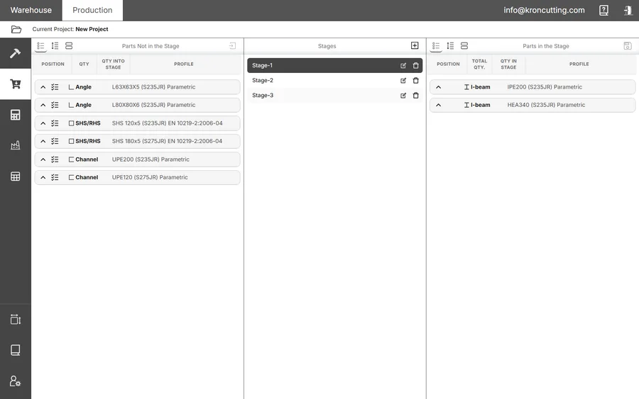
Cutting can be split into stages. You do not have to cut all the material for a job at once.
- In the middle column, create a stage and name it.
- Select parts by clicking them. To move every part of one type, use the checkmarks button on the left of the profile description.
- Select the target stage and click the button in the top-right of the Parts Not in the Stage panel — a square with a right arrow. The parts move across.
In the Parts in the Stage panel, Edit lets you adjust a quantity or remove a part from the stage.
Cutting
Stages and the profiles within them are on the left; the cutting window is on the right.
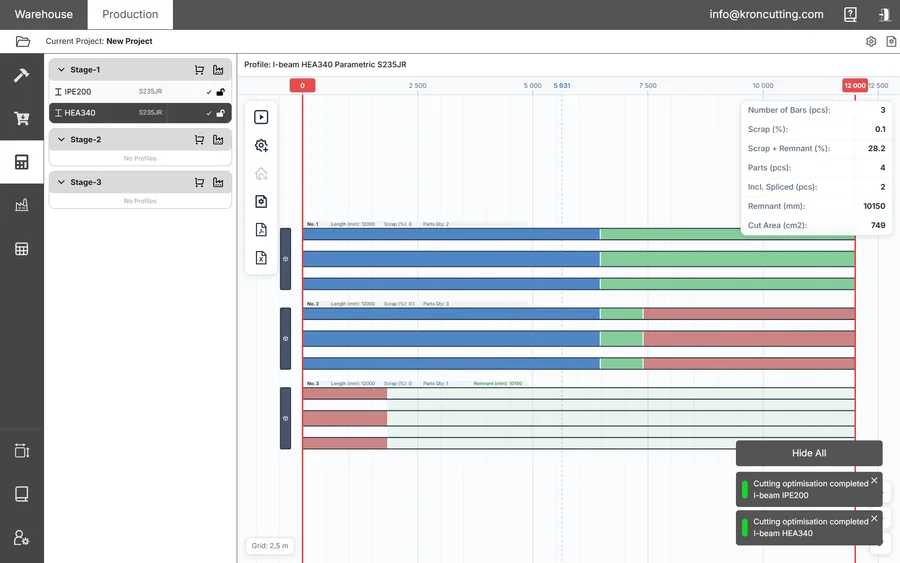
Settings
Set the global cutting settings before you run anything — the button is in the top-right of the window. They apply to every profile.
A single profile can have its own settings: select it and click the gear button on the left of the window. Profiles with individual settings are marked with a gear icon, and the reset button — a row with a cross, top left — puts them back on the global values.
Every parameter is described in the cutting parameters reference.
Reading the result
At the top is a ruler running from −x to 2x, where x is the stock length. Below it, three strips give an unfolded view — left, top and right — without the bottom view.
Parts that have been split into pieces share a unique colour across all their pieces. Left-clicking a colour highlights every piece of that part and greys out the rest; right-clicking the result field clears the selection. Hovering a piece shows its main information.
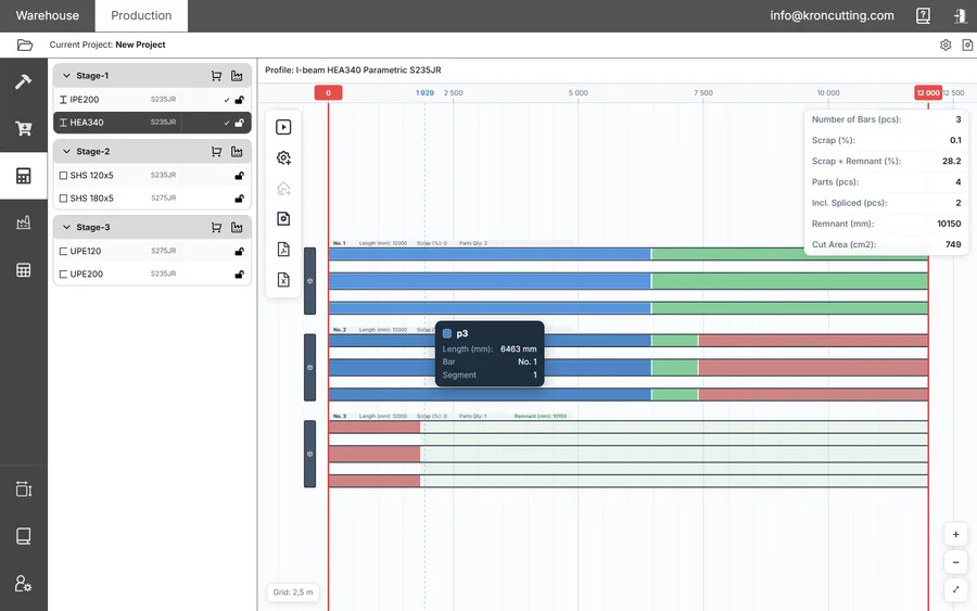
You can keep working elsewhere in KRON while a run is in progress — the screen reports its status, for example that it is calculating the second variant, and a notification appears bottom-right when it finishes.
The characteristics table in the top-right reports the run:
| Figure | Meaning |
|---|---|
| Number of Bars (pcs) | Stock bars consumed by the plan. |
| Scrap (%) | Share of material lost as unusable offcut. |
| Scrap + Remnant (%) | Everything not turned into parts, including reusable remnant. |
| Parts (pcs) | Parts placed. |
| Incl. Spliced (pcs) | How many of those were assembled from more than one piece. |
| Remnant (mm) | Total length of reusable remnant produced. |
| Cut Area (cm²) | Total area of cut, which is what drives saw time and blade wear. |
The button block
What is available depends on the machine:
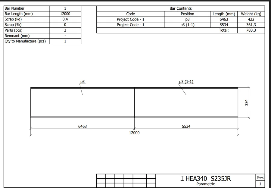
- Bandsaw — Start cutting · Cutting settings · Warehouse (if activated) · Drawing settings · Download drawing · Download process card.
- CNC machine — Start cutting · Cutting settings · Warehouse (if activated) · Download process card · Download CNC result.
Drawing settings
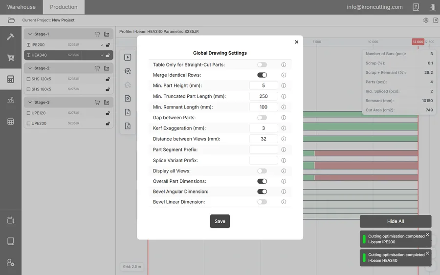
| Setting | What it does |
|---|---|
| Table Only for Straight-Cut Parts | Suppresses parts and dimensions on the drawing when every part on the bar has a straight cut. |
| Merge Identical Rows | Merges consecutive identical rows of the list, showing the quantity and summing the weight. |
| Min. Part Height (mm) | Minimum profile width or height, taking scale into account. Raising it increases the scale and the drawing format. |
| Min. Truncated Part Length (mm) | Minimum length of a continuous segment without bevel cuts when displaying, ignoring scale. |
| Min. Remnant Length (mm) | Shortest remnant shown on the drawing, ignoring scale. |
| Gap between Parts | Shows the gap between parts even where they share a single cut. |
| Kerf Exaggeration (mm) | Exaggerates the gap between parts, taking scale into account, so the kerf is actually visible. |
| Distance between Views (mm) | Distance between the main view and the fold-out views, measured from the part edges and excluding dimensions. |
| Part Segment Prefix | Label applied to the name of a spliced part's piece. |
| Splice Variant Prefix | Label applied to the sequence number of a shop splice of identical parts, on each piece. |
| Display all Views | Shows the top and bottom fold-out views even when they are not required. |
| Overall Part Dimensions | Displays the overall dimensions of parts. |
| Bevel Angular Dimension | Displays bevel angles in degrees. |
| Bevel Linear Dimension | Displays bevel dimensions in millimetres. |
Set these so the drawing is correct and contains only what the cutter needs. A drawing with everything switched on is harder to read on the floor, not easier.
Sending to production, and locking
A completed run that used the warehouse can be sent to production. In the left column, next to the stage name, are the Basket button (purchase request) and the Factory button (production document).
The Factory button opens the Create Production Document window. Select one or more profiles and exactly one production area. Only profiles whose results used warehouse items appear here. Once the document is created the parts disappear from the Cutting tab, so the same part cannot enter cutting twice.
Any cutting result can be locked against changes: in the left column, click the lock on the result row. With the lock closed the cutting-start and settings buttons are hidden. Only the project owner and the administrator can manage this. Lock the final result before sending it to production.
A fully completed run, with all parts moved into production documents, leaves both the Cutting and Adding to Cutting tabs empty. That is the expected end state, not a bug.
Purchase requests
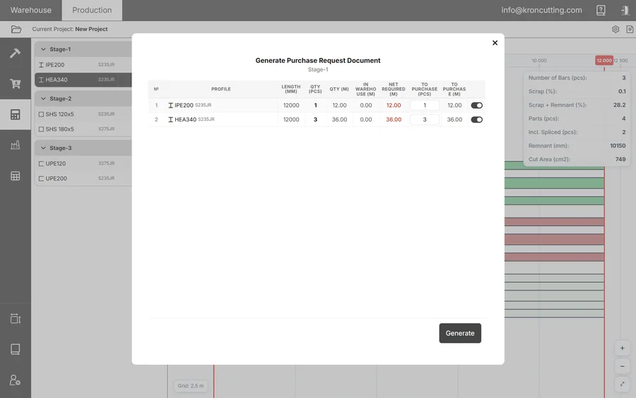
If the warehouse cannot cover the job, run the optimiser without linking to the warehouse and create a Purchase Request with the Basket button. The window lists every profile with a completed run alongside what is already in the warehouse; tick what you need and export it to Excel.
Production documents
Once a production document exists, the results and all their parts move out of the Cutting tab and into the document. Drawings and CNC results do not have to be downloaded at the cutting stage — they are available inside the document itself.
Separate the results of different machines into different production documents: bandsaw work in one, CNC work in another. Mixing them makes the paperwork on the floor harder than it needs to be.
The document is divided by profile. For each profile it shows the stock bar number, length in millimetres, total, manufactured and to be manufactured, plus the Rolled metal on the area and Manufactured bars. Drawings and process cards download from here.
If the required stock bars are not on the area, the To be manufactured field is unavailable.
On the right is the document history, where participants can leave comments. Comments cannot be deleted.
Recording progress
At the end of each shift, or per your own procedure, the executor enters the bars that have been cut and their quantity in the To be manufactured column. Bars are written off the area and parts appear. KRON records which day, who, and how much.
The Manufactured bar reflects the percentage complete, and the document moves to In Progress.
Cancellation and rollback
- Cancellation before physical cutting. The document can be cancelled at any point before cutting starts. All parts return to Parts Not in the Stage on the Adding to Cutting tab.
- Rolling back partial fulfilment. If no remnants have been registered, everything done on the document can be rolled back to the start of production.
- Full cancellation. With no partial fulfilments outstanding — or all of them rolled back — full cancellation returns the parts to Parts Not in the Stage and releases the reservation on the stock bars.
Once a Remnant Receipt or Disposal document has been registered, rollback is impossible. If such a document is confirmed, rollback is impossible permanently. If it is still in Active status and you cancel it, rollback becomes possible again.
If a document is confirmed but you need to free the stock bars a supply request reserved, click Cancel in the production document. The parts will not return to Parts Not in the Stage — only the reservation is released. To use those parts again you will have to add them to the project and run the optimiser afresh.